XP18000 connectors
For a long time I have been trying to figure out the connector sizes on the Energizer XP18000 and XP8000, so that I could make up my own leads. Recently I got hold of a range of plugs and sockets of known sizes and tried them out. I had already measured the O.D. of the plugs, but the pins inside are a lot harder to measure.
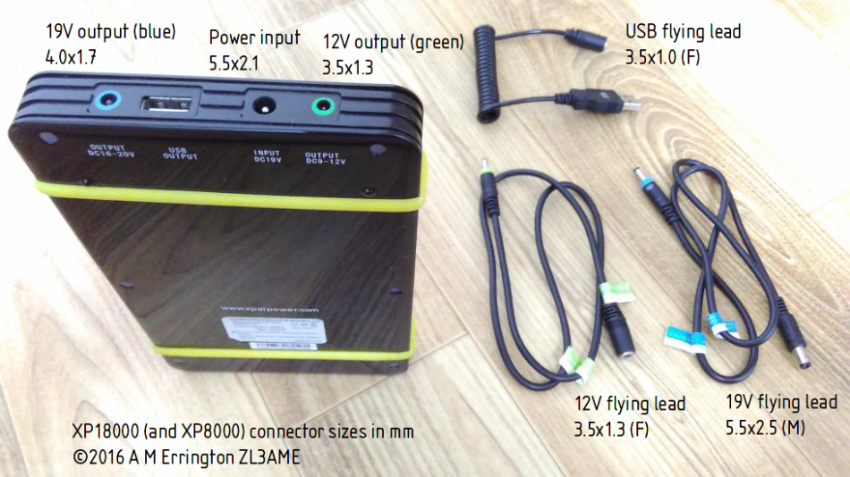
Here’s a picture of the various connectors, and a text summary for search engines.
Input: 5.5×2.1mm
19V output (blue): 4.0×1.7mm
12V output (green): 3.5×1.3mm
USB flying lead: 3.5×1.0mm (F)
19V flying lead (blue): 5.5×2.5mm (M)
12V flying lead (green): 3.5×1.3mm (F)
Note that these sizes have been determined experimentally and may not match the manufacturer’s specifications.
xp18000connectors
Tripod antenna support
I bought a Diamond RH-770 antenna for SOTA, and it’s great! It has a BNC connector, and I can use it with a BNC-SMA adaptor on my VX-2R handheld, or I can connect it directly to the front panel of my FT-817ND. However, if I connect it to the ‘817 I have to stand the radio vertically on end, which actually means I have to carry it and hold it in that position.
That’s okay if I can make contacts quickly, but it’s tiring if I can’t. So I made a small support that I can attach to a camera tripod. It is a plastic plate about 20 x 50 mm with two holes in it. One hole is threaded 1/4-20 for the tripod screw. The other is for a BNC F-F bulkhead connector.
There is a small flat spot on the bulkhead connector to stop it rotating, but it’s hard to drill a mounting hole with a flat part. Instead, I built up a small amount of filler in the hole using baking soda and super glue, which sets hard, and filed it flat.
As you can see from the pictures, construction and assembly is simple, so now I can leave my ‘817 on the ground with a feedline to the antenna on the tripod.
-

- feedline support and antenna packed
-

- support plate and bulkhead adaptor
-

- feedline support and antenna assembled
-

- final assembly on tripod
BrewPi Fuscus first test
After assembling my Son of Fermentation Chiller I connected it up to the Fuscus control box and tested Beer Constant mode at 18 °C with 23 litres of water at 8 °C. The controller started heating the water overnight but it’s only 30 watts so by morning it was only at 15 °C. I changed the setpoint to 17 °C and installed two 2 litre ice bottles.
As you can see from the attached graph the Python script is acting just as an Arduino would, and adjusting the fridge setpoint to keep the beer temperature constant. The heater and cooling fan turn on and off automatically as required. There are undoubtedly bugs to be fixed, but in general the software seems to work.

Son of Fermentation Chiller
In conjunction with the BrewPi controller I have been building a fermentation chamber which I will use instead of a fridge. The basic plans are here: http://www.ihomebrewsolutions.com/son-of-fermentation-chiller/
I had to modify the design to convert to metric, and to fit the cuts into the styrofoam board available here in Korea (known as “isopink” 아이소핑크). Each board is 1800 x 900 mm and 50 mm thick. The outside dimensions are 740 x 510 x 700 mm. The chamber is 410 x 410 x 600 mm. The ice chambers are 180 x 180 x 600 mm each.
Inside, a 5 V 80 mm cooling fan from DX moves the air past the ice bottles. I chose a 5 V fan because it can be driven by a USB power supply which I can simply plug in to the BrewPi cooling outlet.
http://www.dx.com/p/maitech-dc-5v-8-x-8-x-1-1cm-cooling-fan-black-342971
I also installed a 240 Vac 30 W heating tape, which is attached to the inner walls of the chamber and plugged into the BrewPi heating outlet.
Unfortunately I did not take enough care when cutting the boards, so the edges are not quite square. I used some acrylic sealant to fill the gaps, and foam weatherstrip to make a good seal around the door panels. I used childproof drawer clips to clamp the door panels to the side panels, and I made a cut near the rear of the top panel with a taped hinge so that it can be opened separately to change the ice bottles.
Inside the chamber is the fridge sensor and beer sensor. The beer sensor is a cheap waterproof sensor from DX (with a stainless steel end) shrouded in silicone tubing which will allow it to be immersed in the beer. Outside the chamber is the room sensor, which is only used for logging. I did not fit the door switch.
-

- test fitting the brewing vessel
-

- 1800×900 panel marked for cutting
-

- all pieces cut
-

- plastic drawer clips and fan fitted
-

- heating tape attached to wall and sensors fitted
-

- testing
DIY BrewPi Controller runs on Pi Zero!
I finally was able to buy a Pi Zero, which took about 2 weeks to deliver to Korea. Since it is essentially the same as any Pi then any code ought to work. I soldered a 40-pin header to the GPIO port on the Pi Zero and connected a relay board and a connector for the one-wire bus, with a pull-up resistor. The LCD and rotary encoder are optional, because everything can be controlled via the web interface, but it they would work if they were present.
Next, I downloaded the latest Raspbian, Jessie Lite, and set up it up with WiFi. The Zero has only a single USB port, but if that is used for WiFi then it’s easy to ssh in and do everything else. I installed BrewPi and Fuscus from GitHub, and the supporting packages I needed.
The result- it worked! This is probably the smallest, cheapest BrewPi controller that can be built!
Still some work to be done on the software, but I have to wait until I build a fermentation chamber to test the temperature control properly.

DIY BrewPi Controller part 11
Last week I uploaded the first draft of code to my GitHub account. You can see it here. I also took a couple of pictures of the display, showing the standard BrewPi text and layout.
The code is not complete. The menu code (which uses the rotary encoder to make local changes to the settings) is not present. Some low-level code is missing. Some of the core code is broken because, for example, Python does not support the switch statement, so the code must be refactored. There are also probably many bugs lurking. However, most stuff is present, and a lot of features actually work.
In the picture you can see the BrewPi Fuscus control box. Inside the box is the Raspberry Pi with a WiFi adaptor. Above are the three temperature sensors, and the door-open detector switch. The beer sensor is covered with some silicone tubing to act as a thermowell, but this has not been tested yet.
-

- beer constant mode
-

- beer constant mode with cooling outlet on
-

- mode off with web interface mimic display
-

- door open
DIY BrewPi Controller part 10
This weekend marks the occasion where I seem to have the code working. The last step was to implement the LCD code. There is still a lot to do, but I have basically converted the Arduino BrewPi code to Python so that an instance of the BrewPi controller can be run locally on the Pi itself. The webserver and BrewPi server are also running on the Pi.
Instead of connecting to a serial port the BrewPi server connects to a pty (pseudo-tty, e.g. /dev/pts/3) instead of the Arduino serial port. No changes are required to the BrewPi server code as it thinks it is talking to an Arduino. Later I will implement a socket interface, which will require a simple change to the BrewPi server code. This will allow the BrewPi controller to run on a different Pi, or any system which supports Python, one- wire temperature sensors, and GPIO.
This comes at the same time as Elco (founder of BrewPi) announced a new version of firmware for the Particle Photon (which is the core of the new BrewPi Spark). I don’t intend to implement the features found in this firmware as I am only interested in simple temperature logging and control. To be honest, if you want a system that works buy a BrewPi controller from Elco (http://www.brewpi.com). My project is to satisfy a personal interest, although I will be releasing the code on github in case anyone else finds it useful.
DIY BrewPi Controller part 9
This photo shows the lid of the box with the decal in place, covered by a sheet of acrylic. I also found a nice knob for the rotary encoder. The display is showing test data from the three DS18B20 temperature sensors. Upper-left in the picture is the reed switch and magnet which will detect the door-open state.

DIY BrewPi Controller part 8
The LCD is a surplus display from a Nokia 5110. These are available cheaply from dx.com and other sources for about $3. I chose this display because of its price. The original 4×20 LCD is almost three times the price, and more complicated to connect.
The LCD has a resolution of 84×48 pixels. A typical font for this kind of display uses a 5×7 pixel character cell, so assuming a single pixel gap between characters (making a 6×8 cell) we can have 14 characters by 6 rows. I designed a 4×7 pixel font which allows a 17 character by 6 row display. This is enough to show most of the BrewPi LCD information. I modified some Python code I found for the PCD8544 LCD controller to use RPi.GPIO instead of WiringPi.
The rotary encoder is also very inexpensive. I soldered two pull-up resistors to the A and B lines, but it might work without them if I turn on the built-in pullups on the Raspberry Pi GPIO lines. The pushbutton is connected to GPIO3 which has a physical pull-up on the Pi PCB. I wrote a threaded Python module which continually polls the rotary encoder and updates a position variable that can be read at any time.
The LCD is attached to a metal bracket which holds it above the top edge of the opened enclosure. I cut a rectangular hole in the lid of the enclosure so that when the lid is closed the LCD fits into the hole. I printed a black decal on a laser printer with a cutout that exposes the display area but covers the metal surround and PCB.
Next to the LCD hole is a mounting hole for the rotary encoder. The encoder is mounted from inside, with a nut and washer to hold it in place. When the lid is opened the LCD is still visible, and the encoder can be operated from below.
-

- lcd on support bracket
-

- rotary encoder mounted in lid
-

- underside of lid showing lcd opening and encoder mounting hole
DIY BrewPi Controller part 7
The schematic for the Fuscus controller is quite simple. Everything is connected to the Pi’s GPIO header. The LCD is a surplus Nokia 5110 module
like this one. The pinouts can vary depending on the supplier.
The rotary encoder has a built in pushbutton which is connected to GPIO3 (pin 5) so that it can be used to restart the Pi from a halted state. That link is for the bare switch (2 pack) so two pull-up
resistors are needed. An alternative part has pull-ups soldered onto a small PCB with the switch.
The relay module is one of several similar designs. Most of them won’t work with the Raspberry Pi unless they are modified to work with a 3.3V drive signal. For this particular one I decided to short the indicator LEDs so they no longer work.
Finally, an RJ11 socket with screw terminals makes it easy to get the one-wire signals to the outside world.
I am using F-F Dupont cables to connect everything together, however I am considering using this board and this ribbon cable to make it easier to assemble and disassemble. With a single ribbon cable plugged into the GPIO port it would be easy to remove the Pi for another project later.

DIY BrewPi Controller part 6
Here are three images of the mains power assembly. The focus here is on safety. Mains power is dangerous. Please do not attempt this, or any similar construction unless you are qualified to do so.
I decided that if the enclosure was opened the mains voltages should not be exposed. This means it is safe to work on the Raspberry Pi and components inside the enclosure.
In two of the photos you can just see the transparent wiring shield half covering the relays. It is a piece of clear plastic which is inserted at an angle from the top edge of the housing and held in place by the top mounting screw. In the unlikely event of a mains wire or low-voltage wire coming loose the plastic shield should prevent them touching.
The mains cable entering the housing is held in place with a P clip (and a cable gland in the outer enclosure). The live wire is connected to a 10A fuse and then connected to the socket and the relay board. The fuse connections are covered with heat-shrink sleeving. The mains wires are joined with wire nuts.
The socket faceplate is snapped into place, keeping the mains wiring safe inside the housing. The low-voltage wiring exits through a small hole and can be connected to the controller. The mains socket inside the enclosure is intended for a plug-in USB PSU for the Raspberry Pi.
-

- mains wiring connected
-

- unconnected mains wiring
-

- mains wiring enclosed
DIY BrewPi Controller part 5
In this post I have included a block diagram of the project to show how the parts are related, and also to show the changes I have made from the original design at http://www.brewpi.com
As you can see, it’s mostly the same. You put your brewing vessel inside a fridge. The fridge forms an insulated chamber, and, in the original design, a Raspberry Pi and Arduino combination monitors the temperature inside it. To cool the beer, the Arduino turns the fridge on. To warm it up, it turns on a heater or it can even just use the fridge light.
The combination of Arduino and Raspberry Pi is believed to be necessary as the Pi is considered to be unreliable and prone to crashing. The Arduino monitors the temperature and controls the fridge, and the Pi provides a web interface to the system and logs data. The BrewPi project has also evolved into the BrewPi Spark, which replaces the Arduino with a Particle Spark Core.
I don’t believe the Raspberry Pi is too unreliable for this task, so I have started porting the Arduino code to the Pi, using Python. After all, the Pi has digital I/O (for the relays) and can read one-wire temperature sensors. The cost saving is not huge, since an Arduino can be bought for about $30, or a clone for much less, but it removes one layer of complexity. Plus, I want to show it can be done.
On the hardware side, the components are directly connected to the Pi’s GPIO pins. I am using DS18B20 temperature sensors on a one-wire bus. I am using a magnetic reed switch connected to a GPIO for the door-open detector. I am driving a dual mains relay directly from the GPIO, and I have a rotary encoder for user input. I am also using a cheap Nokia cellphone LCD for the display, instead of the BrewPi’s 4×20 OLED display. The Pi can connect to the network via its wired Ethernet port, or a USB WiFi dongle.
My code-name for the project is “fuscus”. It’s a species of brown water python.

DIY BrewPi Controller part 4
I drilled some holes in the case for the electrical wiring. The input is from a mains flex cable from a broken 4-way distribution board. It enters the enclosure through a cable gland and is held in place inside with a P clamp screwed to the electrical socket box.
The switched outlets (with built-in neon indicators) are mounted on the right end of the enclosure. I angled them at 45° so that the cables plugged into them would lead away neatly.
-

- hole for cable gland
-

- holes for socket outlets
-

- cable gland and two outlets to be fitted
-

- socket outlet bases with neon bulbs
-

- overview of enclosure with latches at the top
-

- socket outlets with covers fitted
DIY BrewPi Controller part 3
For safety I wanted to use a properly rated electrical enclosure. Electrical parts are quite cheap here, so I was able to find this box with a hinged lid for about $7. It measures approximately 210mm x 160mm x 130mm externally. Inside is a removable plate for mounting electrical equipment.
I intend the box to be mounted on a wall or on the fridge with the hinge at the bottom so that the lid falls open when the latches are released. This means that the components inside can be inspected without having to hold the lid open.
-

- enclosure closed
-

- enclosure intended orientation
-

- enclosure open
DIY BrewPi Controller part 2
The BrewPi uses two relays to control the mains supply to the fridge for cooling or a heater. An SSR can be used instead of a relay, but I decided a relay is simpler and cheaper. I bought a dual 10A mains relay board for about $3 from DealExtreme.
The relay board has four mounting holes, but the front two, next to the mains terminals, are too close to the terminal housings, so it’s not possible to put a screw there. I made a pair of support pillars 3mm tall from hot-melt glue. These match the 3mm spacers I used for the screws at the rear of the PCB.
The relay board is installed into a standard electrical back box. This electrical box will have a single outlet on the front, for the Raspberry Pi power supply, and wires to the two outlets for the fridge and heater. I wanted to keep all of the live parts inside this box and make it safe. I filled in one of the mounting holes in the back of the box with hot-melt glue as it was below a live trace on the relay PCB, and I cut a plastic shield to put inside the box to keep the live parts and low-voltage parts separate in case a wire should come loose. Finally, I added a 10A fuse, which will protect all of the outlets.
-

- view of relay pcb showing 3mm supports
-

- interior of electrical box showing relay and fuseholder
-

- paper template for low voltage separator shield
-

- underside of electrical box showing one filled hole and three additional mounting holes
-

- construction of hot glue support pillars
DIY BrewPi Controller
We have been brewing beer at home for a couple of years now. We use pre-made beer kits from Munton’s as they are most easily available here in Korea. Brewing beer is a great hobby, and it’s really easy to do. Literally all you need is a bucket. Because I am a geek I decided I ought to make it more complex than necessary and instrument and control the brewing environment. One of the most popular Open Source projects for this is BrewPi, so I decided to make one.
BrewPi uses a fridge as an insulated brewing chamber. Inside the chamber is the brewing vessel (the bucket). The BrewPi software uses Dallas one-wire temperature sensors to measure the temperature of the beer or the fridge and a PID algorithm to turn on the fridge or a small heater to maintain the temperature of the fermentation.
Elco Jacobs, who designed the BrewPi, sells a controller to attach to your own fridge and heater, but he has also released the code as an Open Source project for others to use or learn from. I have decided to build my own based on this software.
If you search the web you will find many DIY BrewPi controllers built in a variety of ways. Some are spliced into the controls of the fridge, others just control the power to the fridge, which is what I plan to do as it means the fridge remains unmodified. So, my BrewPi controller will have two mains outlets, one for the fridge and one for a heater. The outlets will be switched on and off by a pair of mains relays under software control.
The first step I decided to do was modify two electrical sockets to incorporate a neon indicator so that I could see whether the outlet was on or off. This will be useful in the final assembly, but also very useful for testing.
I bought two surface-mount electrical outlets and drilled a 6mm hole in the housing. The hole is filled with hot-melt glue which makes the assembly safe from prying fingers and diffuses the light from the neon bulb. The neon bulbs and dropper resistors were taken from some illuminated mains switches. I extended the wires and covered them in heatshrink sleeving for safety.
Now, when power is supplied to the socket the neon indicator lights up.
-

- single surface mount electrical outlet
-
- neon bulb assembly from illuminated mains switch
-

- final assembly no power supplied
-

- inside socket housing showing 6mm hole drilled
-

- neon bulb installed inside socket housing
-

- final assembly power supplied
